1. Avoid Extremely Thin Walls
Thin walls can deform under cutting forces, especially when machining aluminum or other relatively flexible materials.
This becomes more challenging when a thin feature also has a tight dimensional or geometric tolerance.
Instead of making every wall as thin as possible, consider the actual structural requirement and machining process. Where possible, maintain enough wall thickness for stable workholding and cutting.
If lightweighting is important, pockets and ribs can often be designed to remove material while maintaining sufficient stiffness.
2. Consider Tool Access When Designing Deep Features
Deep pockets and narrow cavities can be difficult to machine because the cutting tool must reach the bottom without excessive deflection.
A long tool with a high length-to-diameter ratio can reduce machining stability and may require lower cutting parameters.
For robot housings and structural components, review:
Pocket depth
Cavity width
Tool clearance
Hole depth
Internal corner radius
Accessibility from different machining directions
If a feature can be reached using a shorter and more rigid tool, the machining process is generally easier to control.

3. Design Clear Datums for Critical Features
Robot components often contain several features that must work together during assembly.
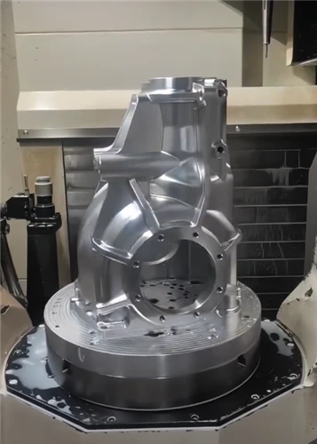
A joint housing, for example, may include a bearing seat, motor mounting holes, shaft bore and locating surfaces. Their relationship can be more important than the individual dimensions themselves.
Use functional surfaces as clear datums and define critical hole locations and geometric tolerances from those references.
This gives the manufacturer and inspection team a consistent reference system.
4. Give Internal Corners a Practical Radius
A standard CNC milling cutter is round, so a sharp 90-degree internal corner cannot normally be produced with a conventional rotary cutting tool.
Adding an appropriate internal radius can make machining easier and reduce the need for special tooling.
For robot brackets, housings and pockets, the corner radius should be considered together with the cutter diameter, wall thickness and functional requirements.
If a sharp internal corner is genuinely necessary, another manufacturing process may need to be considered.
5. Do Not Apply Tight Tolerances to Every Feature
One common DFM problem is specifying very tight tolerances across an entire robot component.
Not every dimension has the same functional importance.
Bearing seats, shaft interfaces, locating features and precision mounting holes may require tighter control, while non-functional external dimensions may be able to use more conventional tolerances.
A practical drawing should identify the features that actually affect assembly or movement.
This helps avoid unnecessary machining and inspection costs while keeping critical interfaces under control.
6. Think About Tolerance Stack-Up
A robot assembly can contain multiple machined parts, bearings, shafts, motors and fasteners. Even when every individual component passes inspection, accumulated variation can affect the final assembly.
For example, the position of a bearing bore, mounting surface and shaft interface may all contribute to the final alignment of a joint.
Before releasing the drawing, engineers should consider how critical dimensions interact across the complete assembly.
Where necessary, use GD&T to control position, orientation, concentricity or other functional relationships instead of relying only on individual dimensional tolerances.
7. Specify Surface Finish Where It Matters
Surface finish should be related to the function of the feature.
Bearing seats, sliding surfaces and sealing areas may require a more controlled finish than external surfaces that are mainly cosmetic.
For many non-functional machined surfaces, an unnecessarily low Ra requirement can add machining or finishing operations without providing a practical benefit.
On the other hand, leaving critical interfaces undefined can create problems during assembly.
A good drawing should clearly identify the surfaces where surface finish affects performance.
8. Specify the Exact Material and Condition
"Aluminum" or "stainless steel" is usually not enough information for production.
Specify the material grade and, where relevant, temper or condition.
Common choices for CNC robot components include:
- 6061-T6 aluminum – lightweight structural parts and general robot components
- 7075-T6 aluminum – higher-strength lightweight components
- 304/316 stainless steel – corrosion-resistant mechanical parts
- Titanium alloys – applications requiring high strength-to-weight performance
- POM and other engineering plastics – bushings, covers and lightweight mechanical components
Material selection should be based on strength, weight, wear, corrosion resistance, operating environment and the required surface treatment.
9. Plan the Part Around the Machining Process
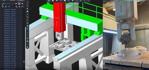
The machining strategy should be considered while the part is still being designed.
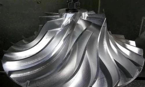
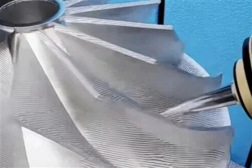
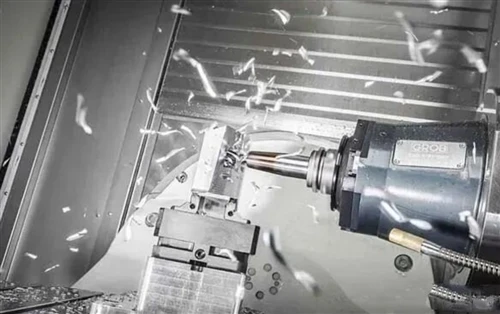
Some robot components are well suited to 3-axis machining, while parts with multiple angled faces, complex surfaces or difficult feature access may benefit from 5-axis CNC machining.
A 5-axis process can reduce the number of setups required for certain geometries and provide better tool access to multiple surfaces.
However, using 5-axis machining does not automatically make every part better or cheaper. The machining method should be selected according to the geometry, tolerance requirements, quantity and production goals.
10. Share Complete Manufacturing Information
A 3D CAD model defines the geometry, but the manufacturer may also need a 2D drawing containing the information that cannot be reliably understood from the model alone.
For a robot component, useful production information can include:
- Material and material condition
- Critical dimensions
- General tolerances
- GD&T requirements
- Surface finish
- Thread specifications
- Surface treatment
- Quantity
- Inspection requirements
Providing complete information at the quotation stage reduces unnecessary clarification and allows the machining supplier to evaluate the manufacturing process more accurately.
DFM Is More Than Making a Part Easier to Machine
The goal of DFM is not to change an engineer's design simply to reduce machining time.
It is about finding a practical balance between function, precision, material, machining method and production cost.
For robot components, this is particularly important because many projects start with prototypes or small batches. A design that is difficult to manufacture can lead to repeated engineering changes, additional setups and longer production cycles.
Reviewing manufacturability before machining gives both the customer and manufacturer an opportunity to solve these issues earlier.
CNC Machining for Custom Robot Components
Jingcheng provides 3-axis and 5-axis CNC machining for custom robot parts, supporting aluminum, stainless steel, titanium and engineering plastics.
Our machining work covers components such as robot joint housings, arm links, brackets, shafts, flanges, motor housings and other precision mechanical parts.
Customers can provide 3D CAD files and 2D drawings for technical review. We can evaluate the part from a manufacturing perspective and provide DFM feedback where a feature may create machining, tolerance or inspection challenges.
We support prototype and low-volume CNC production, making our process suitable for robotics companies developing new mechanisms as well as projects moving toward repeat production.
If you are preparing a new robot component for CNC machining, send us your CAD file, drawing, material and quantity. Our engineering team can review the design and recommend a suitable machining approach before production.